A Quick Overview of Flexible PCB Structure
Keywords: Flexible PCB, Flex Circuits Board
FPC (Flexible Printed Circuit) technology, also known as Flexible PCB technology, is constantly evolving and finding use in the major electronics markets, including consumer, automotive, electro-medical, wearable, telecommunications, and aerospace. The solution based on flexible PCBs provides for a significant decrease in space, weight, and prices when compared to an equal solution based on rigid PCBs because of the connection's flexibility, compactness, and high density of electrical connections that may be obtained. In numerous applications, flexible printed circuits have taken the role of various forms of wire, a lot of which was done manually, bringing down the overall cost of electrical wiring by up to 70%.
The composition of a flexible PCB
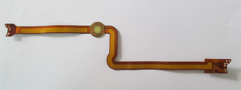
FPCs can be classified as single-layer, double-layer, or multi-layer circuits, much like rigid PCBs. A single-layer flexible printed circuit's primary components are as follows:
The material that is most frequently used, polyimide (PI), has a strong resistance to traction and temperature;
Copper electrical wires that serve as the circuit's traces; a protective finish consisting of cover lay or cover coat; and an adhesive substance (polyethylene or epoxy resin) for securing the circuit's numerous components together.
To create the traces, the copper must first be etched on the Flex Circuits Board. The protective coating (cover lay) must then be perforated to get access to the soldering pads. The components are put together by rolling after a cleaning procedure. The exterior terminals/pins required for the circuit's electrical connection are shielded from oxidation by being submerged in gold or tin for welding. It is important to move to a double-layer or multi-layer FPC if the circuit demands the presence of copper ground shields or has a high level of complexity.
The manufacturing process for multi-layer flexible circuits is essentially similar to that for single-layer Flexible PCB circuits, with the exception that PTH (Plated Through Hole) must be inserted to produce, when appropriate, the electrical connection between various conductive layers. When these materials are combined, a flexible circuit is created. In multi-layer flexible circuits, the adhesive substance is used to connect the individual layers as well as the conductive tracks with the dielectric substrate.
- 1Understanding UL 94V-0 Flammability Rating for Printed Circuit Boards (PCBs)
- 2HDI PCB Market Outlook 2025: Future Prospects, Growth Analysis & Innovations
- 3HDI PCB Design Comprehensive Guide: Mastering High Density Interconnect Technology in 2025
- 4Top 10 Flexible PCB Factories in 2025
- 5Top HDI PCB Manufacturers (2024)
- 6PCB core raw material CCL
- 7IC Substrate | Comprehensive Guide (2021)
- 8How to Make mSAP PCB?
- 9Top 10 IC Substrate Fabricators (2024)
- 10The Impact of Trump's Tariff Policy on Chinese PCB Industry and Countermeasures

- Skype ID: shawnwang2006
- Phone No。: +86-755-23724206
- Email: sales@efpcb.com
- Quick Contact