Common Failure Modes of Rigid Flex PCBs
Rigid Flex PCBs have been gaining traction in modern electronics design, from wearables to aerospace to automotive and medical devices, applications where this unique technology solves specific problems, but all the while causing specific problems that we will be reviewing in our article for today.
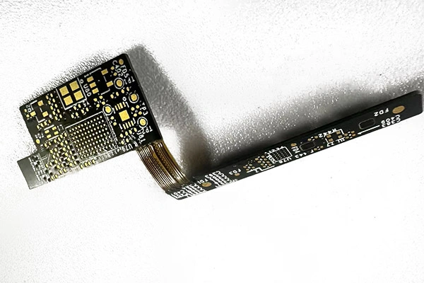
Rigid flex PCBs
Rigid flex PCBs combine rigid and flexible circuit materials, in a three-dimensional arrangement that allows for dynamic movement, but also introducing new sources of stress and of possible failure. The borderlands areas in particular that transition between the rigid and flex boards suffer from mechanical, thermal, and electrical stresses that were not known to conventional PCBs. And when these stresses result in problems and ultimately in failures, the consequences can be severe.
Cracked or Broken Vias
This is by far the most frequent problem faced by a rigid Flex PCB. Vias, creators of electrical connection, are especially vulnerable between the rigid and flexible segments. Repeated bending and poor material matching can ultimately cause microcracks in the copper plating, resulting in intermittent connections or even complete circuit failure. The causes are:
- Excessive bending at the rigid flex interface
- Coefficient of Thermal Expansion (CTE) mismatch
- Bad via designs that are inadequate for Rigid Flex PCB requirements
You will want to reference the IPC-2223 for via design standards specific to this technology. You can also take advantage of teardrop pads and annular rings at transitional areas, and always remember to avoid abrupt rigid-flex interfaces, and try to keep everything gradual.
Delamination for Rigid Flex PCB
Delamination is another critical failure mode in rigid flex PCB construction, when layers separate within your stack-up. This occurs at adhesive interfaces and in the transitional areas between the rigid and flexible regions. Delamination will result in open circuits and ultimately unreliable performance. Its main causes are:
- Incomplete lamination in stack-ups
- Moisture trapped in the process of manufacturing itself
- Repeated thermal cycling or mechanical stress in your applications
Select, if you can, high-quality adhesives and polyimide films for your rigid flex PCBs. Ask your supplier how exactly they implement moisture management and pre-bake cycles. And make sure to always ensure strict process controls during rigid-flex lamination.
Conductor Fracture in the Flex Area for Rigid Flex PCB
The flexible segments, designed for movement, can see their copper traces fracture after repeated flexing if they were not properly engineered. This is another common source of field failures in rigid-flex devices that see usage in dynamic environments. The main causes for these fractures are:
- Too tight a bend radius for a rigid flex PCB application
- Inappropriate copper thickness in the flex region
- Overuse of work-hardened copper
Remember to always follow common guidelines for your bend radius, usually calculated as 10x the flex thickness. Use rolled annealed copper for a rigid flex design that will be aimed at a more dynamic usage. Avoid sharp transitions in your trace routing that will eventually overuse the copper.
Pad Lifting and Trace Peeling for Rigid Flex PCB
Pad lifting and trace peeling are defects from the assembly process, especially when the structure is not supporting the flex region in a sufficient manner. Excessive heat and poor adhesion can ultimately cause pads to separate from the flexible substrate. The main causes are:
- Multiple rework cycles on rigid-flex assemblies
- Poor adhesion between the copper and the polyimide
- Handling rigid-flex PCBs without proper fixturing
You should try to limit both the number of reworks and as well as the soldering temperatures. You should specify the correct adhesion promoters in your rigid-flex design, and remember to support the flex regions during the assembly process correctly.
Solder Joint Failures for Rigid Flex PCB
Solder joint integrity is especially critical at rigid flex junctions where movement and temperature fluctuations are common. A cracked solder joint can lead to an early failure in the assembly process. Look out for:
- Inadequate reflow profile for rigid-flex PCBs
- Poor mechanical support during handling
- Excessive flexing of rigid-flex regions during or after the assembly
You will want to provide support fixtures for flex regions, to optimize reflow and assembly profiles, and do your designs with mechanical strain relief at rigid-flex transitions.
Impedance Discontinuities and Signal Integrity Loss for Rigid Flex PCB
A high-speed rigid-flex PCB is prone to impedance mismatches, especially where traces connect rigid and flex zones. This can degrade performance and ultimately cause a signal loss. Watch out for:
- Poorly controlled stack-up in your design
- Discontinuous ground planes through flex
- Variations in trace width in the flex region
Always use impedance controlled stack-ups for your rigid flex designs. Ensure, in your flex regions, a continuous ground return, and simulate signal paths during the design process to validate them.
Corrosion and Environmental Damage
A harsh environment can eventually cause corrosion on your board when it is not properly coated with good materials. You should be aware of:
- Insufficient conformal coating on your rigid-flex PCB
- Poor material choices for the environment intended for your product
- Moisture or contaminant exposure
Try to use, if you can, high-quality coatings for your designs, and choose the materials rated for the expected conditions of your rigid flex PCB, as well as ensure that enclosures are properly sealed.
Diagnosing Failures for Problems of Rigid Flex PCB
When your board does indeed fail, you can start your diagnostic process by a preliminary visual inspection of the assembly, before moving on to x-ray and microsection analysis of the rigid-flex regions, and ultimately to electrical and impedance testing across rigid flex interfaces. Good communication with your supplier can always give you faster and more accurate root cause analysis.
Strategies for Avoiding These Problems of Rigid Flex PCB
There are also good strategies for tackling these problems, some easy and some more delicate:
Use materials specifically rated for rigid flex PCBs, including adhesives, copper foils and polyimide films. Optimize your design for end-use environment, and adjust accordingly your stack-up, bend radius, trace width and pad geometry.
Pick out a manufacturer with advanced process controls, cleanrooms, Automatic Optical Inspection or AOI, and controlled lamination. These quality checks when done with consistency can prevent many a hidden issue.
During the assembly process, support flex regions correctly. Limit reworks and optimize solder profiles so as to avoid heat-related failures. Make sure operators are properly trained for the handling processes.
Use robust coating and encapsulation to protect the rigid flex PCB that will see usage in challenging environments. Proper sealing and good enclosure design can extend the life of your products in these situations.
Make sure your rigid flex PCBs are rigorously tested before shipment, using electrical testing, thermal cycling and bend testing. Reference your products to a standard like IPC-6013 to make sure they meet quality requirements.
But above all, the success of your project depends on the expertise of your supplier. Work with manufacturers experienced with the fabrication of rigid-flex PCB and willing to participate in DFM reviews.
Rigid flex PCBs enable breakthrough designs and good reliability when conceived, engineered and manufactured with attention to detail, but it faces challenges unique to its nature. We hope you enjoyed our article for today and look forward to seeing you next time!
- 1Understanding UL 94V-0 Flammability Rating for Printed Circuit Boards (PCBs)
- 2HDI PCB Market Outlook 2025: Future Prospects, Growth Analysis & Innovations
- 3HDI PCB Design Comprehensive Guide: Mastering High Density Interconnect Technology in 2025
- 4Top 10 Flexible PCB Factories in 2025
- 5Top HDI PCB Manufacturers (2024)
- 6PCB core raw material CCL
- 7IC Substrate | Comprehensive Guide (2021)
- 8How to Make mSAP PCB?
- 9Top 10 IC Substrate Fabricators (2024)
- 10The Impact of Trump's Tariff Policy on Chinese PCB Industry and Countermeasures

- Skype ID: shawnwang2006
- Phone No。: +86-755-23724206
- Email: sales@efpcb.com
- Quick Contact