PCB is The Circuit Board Changing the World
Keywords: Printed Circuits, Circuits Board
Without the invention of the printed circuit board (PCB), much of the technology we use daily would not be possible. Not only downsizing electronic equipment was made possible by the Printed Circuits but the manufacture of powerful circuitry was also made more cost effective. Today everywhere, printed circuit boards are found—and they still conform to a few basic design principles while their physical characteristics vary enormously.
Using a diagram known as a schematic, we typically design, analyze, and learn about electronic or electrical circuits consisting of component symbols connected by lines. Everything from basic passive components such as capacitors or resistors to sophisticated integrated circuits such as the lines, and microcontrollers are represented by the symbols. Conductive pathways allowing electrical current to flow freely from one portion of the circuit to another are represented by this.
The utter inability to blink an LED, or drive a motor, or do any of the other interesting and useful things, or filter out noise that we expect electrical systems to do is common in all schematics have in common. After all, a schematic is just a drawing. We need to translate its schematic into physical interconnections and physical components to actually accomplish something with a circuit. On a breadboard, Simple schematics can often be realized but the physical realm in the form of a printed circuit board for short is entered by the vast majority of circuit designs.
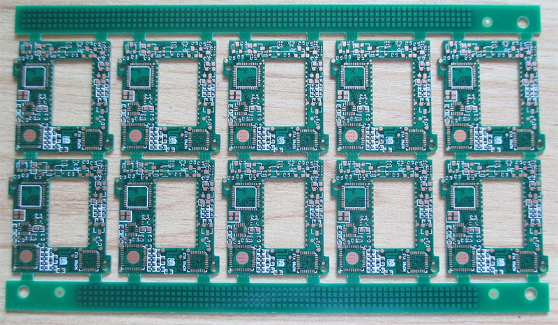
To electrically connect and mechanically support electronic components, Printed circuit boards are used. Etched from copper sheets laminated onto a non-conductive substrate, PCBs use conductive signal traces, tracks or pathways that do not conduct electricity. To the board, Electronic components are then added. Allowing the current to flow through the copper from component to component, etchings are made on its surface.
It’s essential to remember that this hasn’t always been the case while the PCB is of the key concepts in electronics today. When it was invented back in 1936, the PCB revolutionized electrical engineering. To mass-produce electronic devices for the first time, the PCB made it possible as put it simply.
The most common name is Printed Circuits Board but may also be called printed wiring cards or printed wiring boards.
The Printed Circuits Structure
An insulating, rigid, and flat material is a very basic printed circuit board. Thin conductive structure is present in it adhering to one side. Geometric patterns consisting of, for example, squares, circles, and rectangles, are created in these conductive structures. Interconnections are the thin and long rectangles and are equivalent of wires. As connection points for components, various shapes function.
One conductive layer is present in some printed circuit board. The circuit realization in a single-layer PCB will not make efficient use of available area as it is very restrictive. For creating the necessary interconnections, the designer may have difficulty.
The PCB is made easier and compact to design by incorporating additional conductive layers. Over a single-layer board, a two-layer board is a major improvement and having at least four layers benefits most applications. A four-layer board consists of the two internal layers, the bottom layer, and top layer.
Printed Circuits Stackup
The arrangement of insulating and conductive layers in a multilayer PCB is the stackup.
Copper is the conductive material of choice. Pre-impregnated with resin, Prepreg is an insulating material and in composition to the prepreg, the core is similar.
A four-layer structure whenever possible is recommended to be used. You can devote an internal layer to power-supply voltages and one internal layer to the reference potential with the help of a four-layer board. The bottom and the top will be a component layer. This arrangement helps you to achieve enhanced circuit performance and also facilitates PCB design.
Understanding Printed Circuits Terminology and Features
Arising in discussions of printed circuit boards, there’s quite a bit of specialized vocabulary. It is found on PCBs and this section describes physical structures and words are provided to you are so that you can identify them.
A trace is called a conductive interconnection. Pads and through-holes are the connection points for components. Pads are for pins resting on the board surface and through-holes are for pins inserted into holes drilled in the board. Arranging through-holes and pads are present in basic PCB design so that components can be installed properly. Connection of these through-holes and pads are done using traces.
Through-hole components are not all drilled holes. From one PCB layer to another, we often need to transfer a supply voltage or signal. Using conductive and small holes called vias, this is accomplished.
Mounting holes are included in many PCBs, which have no an electrical function but a mechanical function and therefore you need not plate them. Conductive material that has been deposited onto the interior of a drilled hole is indicated by the term plating in this context.
A relatively large section of a PCB layer is a copper pour that is filled with conductive material. To provide a very low-inductance or low-resistance connection between components, Copper pours can be used. This enhances thermal performance.
Consisting entirely of one large copper pour, A PCB layer is called a plane layer. An internal layer is frequently used as a ground plane and by placing vias next to component pins, ground connections are created.
As a circle of copper, a through-hole or via begins and when a drill bit passes through the circle through the circle center of ideally, it becomes a hole. The copper width that remains after the hole has been drilled is called as the term annular ring.
A variety of supplemental information is included in Printed Circuits that have no role in the device electrical functionality. For example, dots indicate proper component orientation, and reference designators uniquely identify components. To keep track of the many circuit boards that accumulate in a lab, project titles or serial numbers help us. This information is called as the silkscreen.
There are several companies offering Printed Circuits online. All you just need to do is find a reliable and reputed supplier that can meet your needs and specifications as well as budget range. It requires a thorough research to get the best source.
- 1Understanding UL 94V-0 Flammability Rating for Printed Circuit Boards (PCBs)
- 2HDI PCB Market Outlook 2025: Future Prospects, Growth Analysis & Innovations
- 3HDI PCB Design Comprehensive Guide: Mastering High Density Interconnect Technology in 2025
- 4Top 10 Flexible PCB Factories in 2025
- 5Top HDI PCB Manufacturers (2024)
- 6IC Substrate | Comprehensive Guide (2021)
- 7PCB core raw material CCL
- 8How to Make mSAP PCB?
- 9Top 10 IC Substrate Fabricators (2024)
- 10What is IPC 4761 Type VII Via in Pad PCB?

- Skype ID: shawnwang2006
- Phone No。: +86-755-23724206
- Email: sales@efpcb.com
- Quick Contact