Dynamic Flexing VS Static Bending in Flexible PCB Design
Flexible PCBs are now a fundamental building block in the electronic devices of today, the enabling factor that allows devices to be lighter, smaller and more reliable than ever. You'll find Flexible PCBs in wearable tech, medical devices and other compact consumer products.
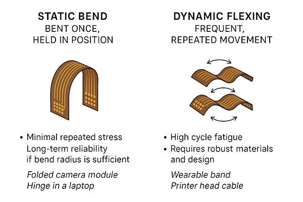
The choice of the correct Flexible PCB strategy will make or break your project. It is a decision that will affect product performance, lifecycle cost and even user safety. In our article for today, we will be taking a look at one of the key aspects of your flexible PCB design: the two sorts of bending actions that your board will be experiencing: the dynamic flex and the static bend.
Dynamic Flexing for Flexible PCBs
A flexible PCB used in a dynamic flexing environment will be subject to repeated movement throughout its operational life. A circuit will flex millions of times during the normal use of the product. Examples include:
- Wearable fitness devices that will be constantly moving with the user
- Printer heads where the board must move in sync with mechanical parts
- Foldable phones that will be bending their flexible pieces every time they open or close
- Robotic joints or industrial automation
Your flexible PCB will be suffering from significant mechanical stress due to dynamic flexing, and possibly develop cracks or trace failures and kill your product before its expected lifetime. You’ll want to prepare your board by good designs that can resist this mechanical stress.
Static Bend for Flexible PCBs
If your flexible PCB is only bent once, usually during the assembly process, and then remains in a fixed posture for the rest of its life, you have a static bend. This is the case with:
- A flexible PCB around the tight corners of a smartphone, a hearing aid, or other wearables
- Routing a flexible board to replace your traditional wire harnesses in car and aircraft designs
- Using a pre-formed bend to accommodate dense and compact electronics
A static bend puts your flexible PCB under stress just once, giving the designer much more liberty with the design. It is still important to handle the board with care during installation to prevent over-bending or creasing.
Comparisons
- A flexible PCB in dynamic flexing applications must brace itself for continuous stress of constant, repeated movement. A static bend is applied once.
- Dynamic applications require high-flexibility materials such as rolled-annealed copper and adhesiveless polyimide. A static bend can content itself with standard polyimide and electro-deposited copper.
- The design for dynamic flexing should embrace the curved trace and avoid sharp corners, and always stay within the confines of its bend radius guidelines. For a static bend, it is still important to conform to bend radius rules for a long and healthy life for your product.
- For dynamic flexing, you’ll want your flexible PCB to go through extensive cycle testing. Static bends are primarily validated for robustness during assembly and installation.
Practices and Tips for Flexible PCB Design
Here are some general considerations and practical tips for the design of your flexible PCB:
- Curved and staggered traces can help immensely in reducing stress.
- Follow the guidelines of IPC-2223 and maintain a bend radius of at least 10x the thickness.
- Take advantage of the qualities of RA copper and adhesiveless polyimide.
- Avoid, if possible, vias and components in the bend area.
- For mission-critical applications, you’ll want to test your board well above the expected cycle life
A flexible PCB in a static bend application will be more tolerant, but you should still keep in mind:
- Avoid sharp corners or abrupt trace changes.
- Always follow the manufacturer-recommended minimum bend radius.
- Make sure the board is properly supported during the assembly process to prevent creasing or kinking.
- Do a proper inspection after the installation to identify any mechanical damage.
Common Failure Modes
Whether your board will be seeing dynamic or static use, your flexible PCB will fail if not properly designed:
- Application of dynamic flexing with repeated flexing can crack your traces, delaminate your layers, or even open your circuits.
- A board subjected to static bend can see creased copper, insulation cracks or assembly-induced breaks.
You can prevent these by selecting the materials most appropriate for your application, adhering to the guidelines we mentioned above, and verifying the capabilities of your supplier.
Flexible PCB Supplier Selection
You should always communicate your intentions to your flexible PCB supplier, telling them whether your product will be undergoing dynamic flexing or remain in a static bend. These circumstances will determine others, such as your stack-up, the most ideal material, and the correct methods of testing. In the process of procurement, you’ll want to ask for cycle-life data for dynamic uses, and clear installation guidelines for static configurations.
We won’t tell you to go out and find the most reputable flexible PCB supplier that you can find. Snobbism has no more place here than elsewhere. The correct solution is the most appropriate solution, and not necessarily the best. You should scout out possible suppliers and then evaluate them based on a fine balance of standardized checklists and experienced intuition, and not simply compare their enumeration of acronyms and their numerological gasconades.
In our article for today we distinguished and compared the two categories of bending that your flexible PCB will be doing: dynamic flexing that will be much more exacting, requiring top-tier materials and adherence to strict design rules, and static bends that are satisfied by correct installation and handling. Specify your flexible PCB requirements, ask a supplier you trust for the appropriate solutions to problems not covered by your textbook cases, and your flexible PCB will be good to go. We hope you’ve enjoyed reading and look forward to seeing you next time.
- 1Understanding UL 94V-0 Flammability Rating for Printed Circuit Boards (PCBs)
- 2HDI PCB Market Outlook 2025: Future Prospects, Growth Analysis & Innovations
- 3HDI PCB Design Comprehensive Guide: Mastering High Density Interconnect Technology in 2025
- 4Top 10 Flexible PCB Factories in 2025
- 5Top HDI PCB Manufacturers (2024)
- 6PCB core raw material CCL
- 7IC Substrate | Comprehensive Guide (2021)
- 8How to Make mSAP PCB?
- 9Top 10 IC Substrate Fabricators (2024)
- 10The Impact of Trump's Tariff Policy on Chinese PCB Industry and Countermeasures

- Skype ID: shawnwang2006
- Phone No。: +86-755-23724206
- Email: sales@efpcb.com
- Quick Contact