Flexible PCB Fabricator

Flexible PCB Fabricator

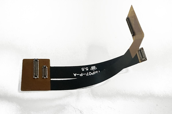
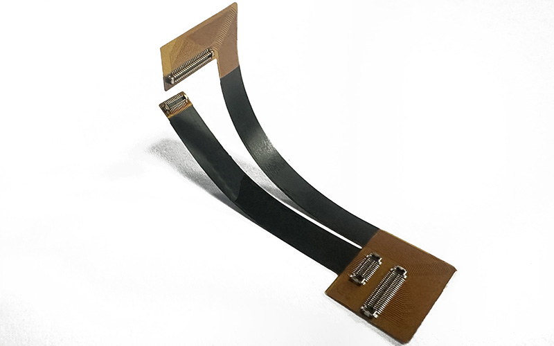
Part No.: E0215060186A

Layer count: 2 layer SAP flex PCB
Material: Polymide, 0.13mm, 1/3 OZ for all layer
Minimum trace: 2.0 mil
Minimum space (gap): 2.0 mil
Minimum hole: 0.15mm
Surface finished: immersion gold
Panel size: 75*15.5mm/1up
Characteristics: Flexible PCB connector, 1mil Polymide, immersion gold, SAP flex PCB, flex connector for Iphone 15

Bend Radius and Flexible PCB Lifespan

Flexible PCBs have become an integral part of modern electronics, the enabling factor of these lightweight and compact devices that we love so much. And today, of the various factors of product durability and the various ways to improve it, we’ll be taking a look at the role of the bend radius.

Flexible PCB Bend Raius

Bend Radius of Flexible PCB

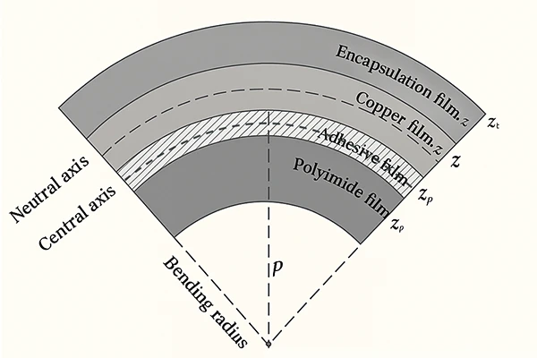
The bend radius is, for a piece of flexible PCB, the radius by which it can bend without suffering mechanical or electrical damage, beyond which the board may crash or even delaminate, and for which the IPC-2223 serve as industry-standard guidelines, specifying the correct bend radius for a given type, thickness and construction.  

When a piece of flexible PCB bends within these limits, its internal stresses remain within the material’s limits, allowing for repeated flexes and permanent bends without damage to the board. But if you were to push beyond these limits, you will end up with:

  • Cracked Copper Traces when thin copper conductors are fractured, and which can ultimately break electrical continuity and cause intermittent or even permanent faults
  • Delamination when the layers of a multilayered PCB separates, especially when adhesives are used
  • Dielectric Breakdown when insulating materials develop microcracks and threaten the board with short circuits or reduced insulation resistance

Getting the bend radius right improves reliability and ultimately reduces warranty claims and downtime, especially with more important flexible PCB applications such as wearables, medical devices and aerospace systems.

 A Minimum Bend Radius of Flexible PCB

The minimum bend radius for a given piece of flexible PCB depends on several factors:

  • PCB Thickness, by which the internal layers are subjected to more significant stress as the thickness increases, and therefore demanding a larger bend radius
  • Number of Layers, in a similar way to the overall thickness, by which a single-layer flexible PCB can have a much shorter bend radius than a multilayered flexible PCB
  • Copper Type, for which the Rolled Annealed (RA) copper is more ductile and flexible than Electro-Deposited (ED) copper
  • Construction Method, for which Adhesiveless constructions are almost always more robust in an application of repeated bending than an adhesive-based construction
  • Flexing Type, of which we distinguish between Static Flexing where circuits are bent once during assembly and remain in this posture, and Dynamic Flexing where a flexible PCB bends repeatedly during operation, such as for applications of folding phones and printers. Dynamic Flexing is the type that will be requiring a larger bend radius whereas Static Flexing can do with a tighter bend radius.
  • Environmental elements, such as high temperatures, humidity and exposure to chemicals, can all reduce a material’s ability to withstand bending stress

IPC-2223

The rule of thumb for flexible PCBs from IPC-2223 is:

  • A minimum bend radius of 6 x overall thickness for single-layer flexible PCBs of static bend
  • A minimum bend radius of 12 x overall thickness for multilayered flexible PCBs of static bend
  • A minim bend radius of 100 x overall thickness for dynamic flexing

Maximizing Lifespan

Here are some tips for maximizing the lifespan of your flexible PCBs:

  • Use RA copper for circuits that will undergo frequent bending
  • Avoid traces perpendicular to the bend, prefer instead gentle curves and staggered traces between layers
  • Apply proper cover layover critical bend areas to provide mechanical protection
  • Add stiffeners to regions that should not be bending to prevent unintentional stress in critical zones
  • Avoid vias in bend areas in order to reduce the risk of cracking

Testing and Validating Bend Radius

The various testing methods for flexible PCB that have been standardized across the industry are:

  • Visual Inspection: a basic but effective preliminary inspection for cracks, delamination or insulation damage after bending
  • Bend Cycle Testing: flexing the circuit repeatedly to simulate real-world use and detect early failures
  • Electrical testing: measuring and comparing continuity and insulation resistance during and after mechanical stress

Mistakes to Avoid

  • Do not ignore this minimum bend radius, because pushing your flexible PCB beyond is a guaranteed early failure
  • Do not overlook material properties. Using ED copper or thick adhesives in dynamic application can very well lead to cracking
  • Do not forget that your flexible PCB will also be bending on the assembly line, and, if necessary, decrease your bend radius and adjust your design accordingly


The bend radius is an important consideration in the design for your flexible PCB, and one of the determining variables of its lifespan. In our article today we enumerated the most important factors that decide this bend radius: the thickness, the number of layers, the type of copper and the type of construction, and the amount of flexing that flexible PCB will end up seeing. Remember to take into consideration this important value in your flexible PCB project and we look forward to seeing you next time.


Frequently Asked Questions for Flexible PCB

What is the minimum bend radius for a generic piece of flexible PCB?

For a single-layer flexible PCB in a static application, the minimum bend radius would be 6 times its overall thickness. For dynamic flexing, it will have to be 100 times or more.

What happens if I exceed minimum bend radius?

Exceeding the minimum bend radius will result in copper cracking, even delamination, and ultimately in early circuit failure.

How can I test if my flexible PCB design meets bend radius requirements?

Use visual inspections, bend cycle testing, and then electrical continuity tests. These tests will be able to verify whether your product can indeed execute the minim bend radius that you got on paper.

Iphone 15 Flexible PCB Connector